
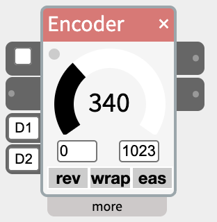
A rotary encoder is a knob that turns forever in either direction and clicks as it turns. Unlike a potentiometer (read with AnalogIn), it has no ends and no fixed position: it only reports that it moved, and which way. The Encoder widget turns those clicks into a value that goes up when you turn one way and down when you turn the other, staying between a min and a max that you choose. Use it for menus, volume or brightness controls, scrolling through choices, or any setting you want to nudge by small steps.
Encoder needs a board running NTK’s CircuitPython Firmata firmware, which is included with your NTK download (the CircuitPython/ folder, with its own setup README), connected over Network (WiFi). The board counts the clicks itself, so none are missed even when the knob is spun quickly. A board running standard Arduino Firmata does not understand the Encoder widget. The widget speaks ConfigurableFirmata’s encoder protocol, so an Arduino running ConfigurableFirmata with encoder support should work too, but that hasn’t been tested.
Contents
- Wiring
- How it works
- Testing without an encoder
- Buttons
- Setting edges
- Settings in the more panel
- Standalone patches
- Notes
- Example patches
Wiring
An encoder has two signal pins, usually labelled A and B (or CLK and DT on a module), plus ground. The widget’s defaults are D1 and D2, which is the Grove port marked A1/D1 on the Seeed XIAO expansion board.
Bare encoder (three pins in a row, A–C–B, with the common pin in the middle):
| Encoder | Board |
|---|---|
| A (outer pin) | D1 |
| C (middle pin) | GND |
| B (outer pin) | D2 |
Add a 10k resistor from each signal pin to 3V3 if the count doesn’t move or jumps around.
Encoder module (e.g. a KY-040, labelled CLK / DT / SW / + / GND):
| Module | Board |
|---|---|
| CLK | D1 |
| DT | D2 |
| + | 3V3 |
| GND | GND |
| SW | any free pin, read with a DigitalIn widget |
Power a module from 3V3, never 5V: its built-in resistors connect to whatever it’s powered from, and the board’s pins aren’t made for 5V.
It doesn’t matter which signal pin goes to D1 and which to D2. If the value goes the wrong way when you turn, swap the two wires or turn on rev.
Many encoders also click down like a button. That push switch is a separate pin, read with its own DigitalIn widget. The switch connects that pin to GND when pressed, so leave the DigitalIn’s pull-up option on (the default) and pressing reads as on.
How it works
- Tick the checkbox at the top of the left edge to connect to the board. The dot in the top-left corner of the dial shows the connection: grey when off, blinking amber while connecting, green when the board is counting, red if the board couldn’t start the encoder (hover over the dot, or open the “more” panel, for the reason).
- Turn the knob. Each click adds step to the value or subtracts it, depending on the direction. The value shows in the middle of the dial and comes out of the out outlet.
- Send each turn with the step outlet. Each click also comes out of the step outlet as how far it moved: step for a click one way, minus step for a click the other way (so +1 and -1 with the default step of 1). It shows the turn and then goes back to 0, so two clicks in a row arrive as two separate changes. Clicks made faster than NTK can send them are added together and sent as one turn. min, max and wrap don’t affect it, so it keeps sending even when the value is held at an end, and a value arriving at set doesn’t send anything. Use it when another widget keeps the real value and only needs to hear “a bit more” or “a bit less”, such as DCC Throttle’s step inlet. For most uses, like volume or brightness, use out.
- Set the value from another widget. Whatever arrives at the set inlet becomes the current value, and turning carries on from there. Use it to reset to a starting point, or to jump to a preset.
- Min and max keep the value in range: by default it stops at the ends, 0 and 1023.
- The value is saved with the patch, so reopening it carries on where you left off.
Testing without an encoder
You can build and check a whole patch with no hardware attached:
- Scroll the mouse wheel over the dial to step the value up and down, as if you were turning the encoder. Each wheel notch is one click.
- Drag the dial to jump straight to a value. The step outlet sends however far the dial moved.
Buttons
Under the dial:
- rev — reverse the direction, so the turn that counted up now counts down.
- wrap — instead of stopping at min and max, wrap around: one click past max goes back to min, and one click below min goes to max. Handy for menus and anything circular.
- eas — easing. The out value glides toward the new value instead of jumping, for smoother movement when driving a light or a motor.
Setting edges
Encoders don’t all report the same number of counts per click. The edges setting in the “more” panel tells the widget how many counts make one click. If it’s wrong, the value moves too far per click, or only moves every few clicks.
To find the right number:
- Leave edges at 1 (the default) and step at 1.
- Turn the encoder exactly one click.
- See how far the value moved, and set edges to that number:
| One click moves the value by | Set edges to |
|---|---|
| 1 | 1 (already right) |
| 2 | 2 |
| 4 | 4 |
For a more reliable answer, turn exactly 10 clicks and divide how far the value moved by 10.
Starting from 1 is the safe choice. An edges setting that’s too low makes each click move the value several steps, which is obvious and easy to fix. One that’s too high makes the value move only every second or fourth click, which looks like clicks are being skipped.
The right number depends on both the encoder and the board, so check again whenever you change either one. For example, a KY-040-style encoder on a Seeed XIAO ESP32-S3 needs 1.
Settings in the more panel
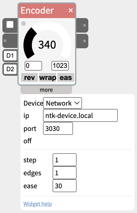
- Device — set this to Network, with the board’s address and port (or use the left panel’s default Device, which is applied to new hardware widgets automatically). Changing the device, address or port unticks the checkbox; tick it again to reconnect.
- Status — what the connection is doing, including the reason if the board couldn’t start the encoder.
- step — how much each click adds or subtracts. It can be a fraction, e.g.
0.1. - edges — encoder counts per click. See Setting edges above.
- ease — how slowly the eas button glides. Higher is slower.
The two pin fields on the left edge, under the set inlet, are pin A (top) and pin B (bottom). Changing pin A moves pin B to the next pin along. Change pin B afterwards if your wiring is different.
Standalone patches
Encoder works in a patch pushed to the board. The board counts the clicks and applies step, edges, min, max, rev, wrap and easing itself, and a value wired into set still sets the count. The step outlet works the same way on the board. In Monitor mode the widget shows the board’s count as it changes.
Notes
- The value doesn’t change when I turn the knob. Check that the checkbox is ticked and the dot is green. If the dot stays amber, the board isn’t answering; check its address. If it turns red, hover over it for the reason, usually a pin that doesn’t exist on the board.
- The value only changes every few clicks. edges is set too high. See Setting edges.
- The value jumps several steps per click. edges is set too low, or step is larger than 1.
- It counts the wrong way. Turn on rev, or swap the wires on D1 and D2.
- The count jumps around on its own. The signal pins are floating: add the 10k resistors described under Wiring, or use an encoder module, which has them built in.
- The value stops at 0 or 1023. It has reached min or max. Change them, or turn on wrap.
Example patches
- Encoder → AnalogOut — set an LED’s brightness by turning a knob, with min 0 and max 255.
- Encoder → Servo — position a servo in steps, with min 0, max 180 and step 5.
- Encoder → Display — show the count on the board’s OLED, a handy way to check edges with the board on its own.
- DigitalIn (encoder push switch) → IfThen → Encoder set — press the knob to reset the value to a starting point.